Before we get down to buisness i would first like to say that I am in no way responsible for any problems or blown parts as a result of following this tutorial, do so at your own risk! Not every bike is the same electrically and not every bike uses the same winding pattern. Do not attempt to rewind your stator unless you feel confidant in your ability to do so correctly. errors in the number of turns or placement of the poles for each phase can result in your voltage regulator/recitfier letting the magic blue smoke out.
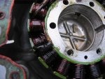
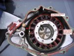
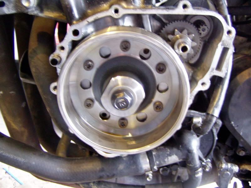
lets briefly go over stators and how the stator works in the alternator. a alternators job is to turn mechanical power from the engine into electrical power for the lights, turnsignals and most importantly the ignition. the alternator usualy does this with a permantly magnetic rotor
![Image]()
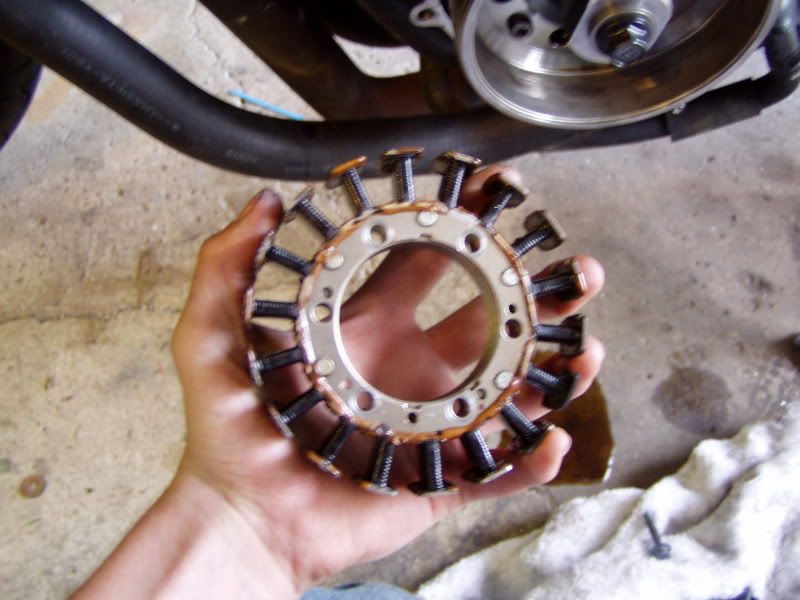
and a electromagnetic stator.
![Image]()
(unwound)
as the rotor rotates around the stator, the magnets in the rotor react with the coiled wire and iron in the stator (you can see the individual magnets in the pic of the rotor if you look closely). the poles on the rotor alternate north and south and as such alternate the voltae coming out + and -. this is done at a rather high frequecny based on the engine's RPM. these alternating currents (might be voltage but i dont know for sure) are then picked up by your voltage regulator, turned into rectified DC current and limited in voltage. that power is then used for all your bikes electrial needs and the excess power is stored in the battery.
If anyone has ANY questions AT ALL, feel free to PM me or shoot me a email at mbxofna@yahoo.com ill do what i can to help
lets briefly go over stators and how the stator works in the alternator. a alternators job is to turn mechanical power from the engine into electrical power for the lights, turnsignals and most importantly the ignition. the alternator usualy does this with a permantly magnetic rotor
and a electromagnetic stator.
as the rotor rotates around the stator, the magnets in the rotor react with the coiled wire and iron in the stator (you can see the individual magnets in the pic of the rotor if you look closely). the poles on the rotor alternate north and south and as such alternate the voltae coming out + and -. this is done at a rather high frequecny based on the engine's RPM. these alternating currents (might be voltage but i dont know for sure) are then picked up by your voltage regulator, turned into rectified DC current and limited in voltage. that power is then used for all your bikes electrial needs and the excess power is stored in the battery.
If anyone has ANY questions AT ALL, feel free to PM me or shoot me a email at mbxofna@yahoo.com ill do what i can to help